This “How to solder” guide is not going to be one of those guides where I boringly and very technically explain each particular step in the procedure. And then you copy what I do – you may repeat what I am doing but you will forget it as soon as you finish your soldering project.
The idea of this guide s that you learn the logic and process that is involved in soldering.
This way you will be able to practice how to solder and build other soldering projects.
Once when you understand a basic of soldering and get familiar with soldering tools you will be able to build stunning circuit boards or repair of a complex PCBs. It doesn’t have to cost a lot to start learning how to solder.
The most critical skill in electronics is soldering. Learning how to solder is not a difficult task. All information and the tips in this guide comes from years of experience.
For some people soldering is a simple task performed with a soldering iron and a piece of solder. However, the soldering of the printed circuit board is a fine art of making reliable electrical connections. Knowing how to solder is handy when you building or repairing electronic devices and circuit boards.
Soldering is the process of joining certain metals by melting and flowing a filler metal alloy into the joint. Melted metal alloy, usually called solder, makes an electrical and mechanical connection in the joining place.
Safety precautions
The soldering process produces fumes. Use a smoke extractor (also known as a smoke absorber) or solder in a well-ventilated area. A smoke absorber absorbs most of the smoke from the flux and cleans the air. The smoke absorber consists of a fan and a black carbon filter. In any case, avoid inhaling the smoke.
Flammable liquids and materials should be kept away from the working area. Rosin flux is flammable since alcohol is used as a solvent in the flux.
Don’t touch the tip of the soldering iron since it is very hot.
Don’t place hot soldering iron down on the workbench or anything other than an iron holder
Hold wires to be soldered with tweezers or pliers
Never solder any circuit that is connected to power. If it is plugged into a wall unplug it before soldering..
Wear safety glasses to protect your eyes.
Don’t solder anything directly on battery leads
Preparation for soldering with a soldering iron:
Before you start soldering, you need to prepare a soldering tool and accessories.
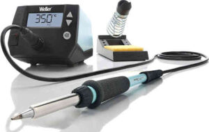
In this ‘How to solder” guide we will use the WE1010 Weller soldering station which comes with a base unit, soldering iron and a stand with a cleaning sponge. It has a temperature controller and digital display on the base unit.
Select and install the proper iron tip for your application while the soldering iron is still unplugged and cold.
In this guide, we will be using an iron tip for general use on the circuit board: 1/16 inch (1.6 mm) chisel tip.
Unscrew the nut that holds the tip.
Remove the existing tip and insert a new tip in soldering iron.
Screw the nut back with your fingers or pliers.
Finally, you are at the point where you are about to turn on your soldering iron and start learning how to solder.
Plug your soldering station in a wall outlet. Turn it on and set the desired temperature on the base unit in the range of 700-750 degrees F (370- 400 °C).
If your soldering iron is set to a higher temperature then soldering time should be shorter and vice versa. You can start with setting the iron to 700 °F (370 °C) and later when you improve your soldering skills you may increase the temperature.
Turn on the smoke absorber if you have one.
Solder melts at around 370 °F (188 °C).
Solder is an alloy of two metals; usually tin and lead at a rate of 60/40 (60 tin, 40% lead) or 63/37. Solder alloy could be a combination of other metals.
A variety of solder alloys are used in the soldering industry, however, a huge majority of solder alloys are still tin-lead alloys.
Trend is to avoid the use of lead in alloys and replace it with another metal such as silver.
Leaded solder alloys offer a low melting point and increased reliability over lead-free solder alternatives.
In this guide, we are using 60/40 solder wire with rosin flux core.
Dampen the sponge in the iron holder with water (the sponge should be moist).
Clean the soldering area and dirty components. All components must be clean and free from oxidation, grease, and other contamination. The solder will not stick to a dirty component or dirty area on the printed circuit board. You can use an approved solvent or cleaner.
Tip of the soldering iron must be clean as well. A clean tip is one of the main requirements for successful soldering.
Clean the tip of soldering iron by wiping on a damp sponge. Wipe all of the tip’s surfaces by turning the iron a few times. You will hear a sizzling sound when iron comes in contact with a damp sponge.
Don’t leave the soldering iron in contact with a sponge longer than necessary. The sponge will act as a
heat sink and may cool the iron tip.
Don’t use the same sponge for a long time. After some time the sponge becomes contaminated as well and that contamination can be reattached to iron.
Replace new clean the sponge regularly.
If necessary, use brass wire tip cleaner to clean the tip of all residual solder and oxidation by inserting the tip and twisting a few times.
Before soldering, the tip of soldering iron should be “tinned” or, in other words, coated with a thin layer of liquid solder. This layer of solder improves heat transfer between the soldering iron and solder joint.
Apply some solder on each side of the tip end and then wipe the excess solder on the damp sponge.
Place soldering iron back in the stand.
If you are soldering static-sensitive components such as CMOS components, wear anti-static protection (ESD) like a wrist strap on this image.
The other end of the wrist strap should be connected to the ground.
It is a good idea to ground yourself to avoid any damage that static may cause.
How to Solder Circuit Boards
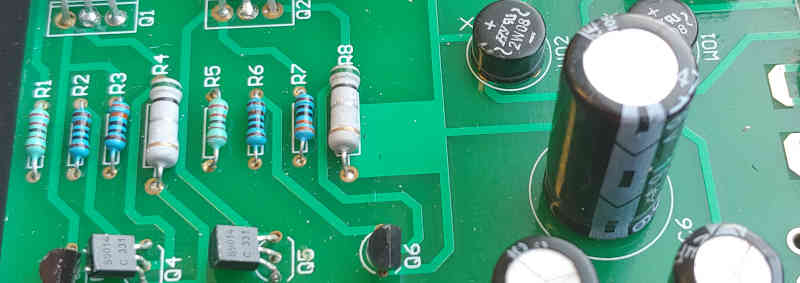
Spread component’s leads to fit through the circuit board. Insert component into a metalized hole of the circuit board. The component should be flush with the front of the circuit board.
Flip the board over and bend the component’s leads a little bit outward to prevent the component from falling out. There is no need to bend leads too far down to the surface of the PCB. Don’t bend leads more than 45° outward.
Don’t insert all electronic components at once. Start with smaller components, one at a time.
Some components such as electrolytic capacitors, LEDs and diodes are polarized so you need to pay attention to which way you insert them in the board.
Other components such as resistors are not polarized so it doesn’t matter which way you insert them.
Integrated circuits (IC) have several leads IC leads. You can bend only one lead to keep IC from slipping from the board and then start soldering the rest of the leads.
I always recommend using sockets for ICs. You solder the socket to the circuit board and then plug IC into the socket. That way is much easier to replace IC when for any reason it doesn’t function properly.
Most of the solder wires come with a core that contains flux. If you are going to use this type of soldering wire (that contains flux) you do not need to apply any additional flux to the soldering joint.
However, if you are going to use a solder wire which doesn't contain flux then it is recommended to apply a small amount of solder flux to the solder joint at this step.
Take soldering iron from a stand and hold it as a pen.
Between uses, a soldering iron is kept in a stand.
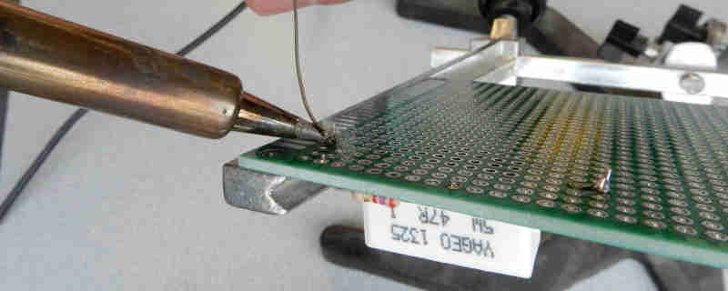
Position the iron’s tip gently on the joint and hold for few seconds. Make sure it touches both the track on the circuit board and the component lead. Hold soldering pencil at a 45-degree angle to circuit board surface and apply gentle pressure.
One of the most common mistakes that beginners in soldering make in this step is that they strongly push soldering iron to the soldering joint hoping that the stronger they push the more heat will be delivered to the soldering joint. This can end up damaging the circuit board or soldering pencil.
There is no need for hard pressure - just position the tip gently to the soldering joint. Downward pressure against soldering joint must be minimized to avoid damaging, burning or lifting soldering pads or thin copper conductors on the circuit board.
Continue heating the soldering joint and feed some solder. Solder is an alloy of two metals, usually tin and lead. The solder can be in form of solder wire or solder paste.
It is important to select a soldering wire with a proper diameter. This will help to control the amount of solder being applied to the solder junction. Soldering wire with a small diameter should be used for a small solder joint and soldering wire with a large diameter should be used for a large solder joint. In this guide, we will use soldering wire with a 0.8 mm (0.031”) diameter.
The main cause of bad soldering is not applying the proper amount of solder.
As the solder melts the flux begins to flow in the joint, cleans the soldering area and prevents oxidation of connecting metals. Don’t apply solder directly to the tip of the soldering iron.
Heating one part but not the other will result in poorly formed joints. The solder should melt and flow smoothly onto the track and component lead to form a volcano shape.The solder should always be applied to the upper portion of the solder junction – it may be lead of an electronic component, wire or terminal. That way the upper surface (and not the soldering iron) will melt the solder. Gravity will help the solder to flow to the lower portion of the solder junction.
It only takes a couple of seconds to make a perfect joint. The heating period depends on the temperature of your soldering iron and the size of the joint. If you keep soldering iron on the component’s lead too long you may damage the component or pads on the circuit board. Applying too much heat to a temperature-sensitive component may damage it.
It is recommended to hold a lead of such a component with metal tweezers. Tweezers act as a heatsink and take the excess heat and therefore protects components from heat damage. In addition, if such a component has longer leads, it is better to first solder leads and then trims the extra length of them. Longer leads will draw some heat away from the component.
Grab the lead with tweezers between the solder joint and the body of the component. Holding the component’s lead between the solder joint and the end of the lead doesn’t protect a component from heat damage at all.
After a few seconds remove the solder, then remove the soldering iron. Wait for a few seconds to allow the joint to cool down.
Always clean and tin the iron’s tip when you are finished with soldering. Proper tinning will prevent oxidation and significantly extend tip life.
Cut the surplus wire leads off with small cutters. Don’t cut into the solder joint - just trim the surplus wire leads at the top of the solder joint. When you cut these wire leads the pieces of wire will fly away from the circuit board. To prevent this from happening is to push the end of the wire lead with fingers of one hand and cut them with the other hand. This will shield your face from the wire being trimmed.
Inspect soldered joints.
Adjacent components may be bridged together or the joint may need additional solder for good electrical continuity. Shake the leads softly to make sure that there are no loose gaps in joints.
Good soldering joint is bright and shiny while bad solder joint has a frosted appearance. Good soldering technique combined with a little effort spent to make a perfect soldering joint may save a lot of time later in troubleshooting a defect caused by a bad soldering joint on the circuit board.
Cold solder joints are caused by insufficient heat. It happens when soldering iron touches only component lead or only a pad on the circuit board but not both of them simultaneously. Therefore, the solder sticks only on a component lead or only on the pad - there is no connection between the component lead and circuit board. Cold solder joint could be easily fixed by re-soldering with a proper soldering technique. Sometimes is necessary to add a little bit of solder to the cold solder joint. Adding a little bit of solder flux on top of the cold solder joint before re-soldering it may make this repair process even smoother.
Adding too much solder to the solder joint can results in a “bridging” to a neighbouring pad. This bridge makes a short connection between two solder joints. The bridge may be removed by simply passing hot soldering iron between those two soldering pads. If this technique doesn’t help, then remove the bridge with a solder wick or solder pump (solder pump is also known as solder sucker).
Remove rosin flux residues from the surface of the solder joint with isopropyl alcohol or flux remover pen.
Use a small brush or a cotton swab to apply isopropyl alcohol on the flux residues.
Rinse the area with distilled water. It is better to use distilled water than tap water. Tap water may leave small stains on the circuit board since it contains minerals.
How to Solder Electronics
How to solder electronics depends on the package and size of electronic components to be soldered and soldering tools we are using.
Over the past several years, technology has caused dramatic changes in the way electronic devices are designed and this has changed ways how to solder electronics. In too many cases, the soldering skills and soldering techniques have kept pace with technological improvements in the design of electronic devices.
There are major differences between techniques and processes used in the manufacture of circuit boards and those required for repair them. With the advent of miniaturization of electronic components and switching from through-hole parts to surface-mount packages, the technique of soldering has significantly changed.
Soldering surface-mount components to the circuit board are not the same as soldering through-hole components.
When soldering small surface-mount components you must have a microscope or at least a magnifier lamp.
A hot air soldering tool is sometimes the only option for the removal of small surface-mount ICs.
The most difficult components to solder are BGA surface-mount components. The BGA component has no leads - all contacts are hidden at the bottom of the BGA component.
When soldering surface mount components you should use a temperature controlled soldering iron. Choose a small conical solder tip 3/64 inches (1.2 mm).
Apply a little bit of solder to pads on the circuit board where you want to solder the component. This process is known as the tinning of pads.
Using a pair of tweezers, pick up the component to be soldered and place it over the tinned pads. Continue to hold the component with tweezers and apply soldering iron to the connection. Remove soldering iron after a couple of seconds.
Now when one side of the component is soldered to the board you don’t need to longer hold the component with tweezers. Repeat this step to the other end of the component.
How to Solder Wires
Soldering two wires together is an easier process than soldering components on a circuit board. That means learning how to solder wires is not difficult at all.
There are two kinds of insulated wires: solid and stranded. The solder easier penetrates in stranded wires.
Wires come in different sizes (AWG) depending on their thickness. For example, speaker wires are much thicker than headphones wires.
When soldering wires, it is handy to have some kind of tool that holds wires together. Otherwise, it would be challenging to solder two loose wires since you hold soldering iron with one hand and you are adding the solder with the other hand.
The third hand tool (also known as soldering helping hand) is an excellent help for holding wires securely.
This tool is very popular and cheap.
There are many variations of a third hand tool available on the market. Any kind of third hand comes with two alligator clips at end of long arms and a weighted base. The third hand tool may come with a magnifier.
First, start with preparing wires for soldering.
Plastic insulation should be removed from the end of both wires. Remove at least 1/4 of an inch. Use wire strippers to remove insulation such as one on the picture.
Do not use an executive knife to remove insulation since a knife can damage a wire.
If you are going to use heat shrink over solder connection make sure to put a shrinking tube on the wire before soldering. Once you solder two wires together, it may not be possible to insert a shrink tube. That is the case where the other end of the wire is already attached to the circuit.
Then you should make some kind of solid mechanical connection between wires.
If you are working with stranded wires, you can simply twist wires together.
If you are working with tick solid wires, you should make a loop as shown in the picture.
Trim the ends of wires if they are sticking out of the connection.
This mechanical connection of wires prior to soldering increases the strength of a final joint between wires.
Tin each wire prior to soldering with a thin layer of solder.
Using a third-hand tool secure both wires. Take a hot soldering iron and apply heat to the connection. Make sure that soldering iron touches both wires simultaneously.
After a couple of seconds feed some solder to the connection.
Sini Saja is a passionate Electrical Engineer with over 40 years of experience in the electronics industry and in 3 countries. He holds B. Sc. in Engineering and is a member (P. Eng) of the Association of Professional Engineers of Canada.
Sini Saja wrote several articles on Instructables.com and EzineArticles.com. He earned a silver medal for over 1 million views on Instructables. See profile here.