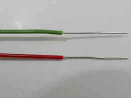
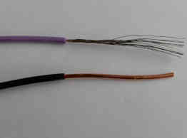
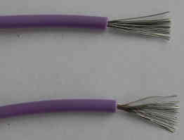
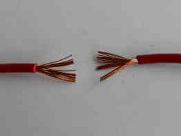
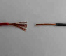
The solid wire has only one strand while stranded wire has multiple strands twisted together.
The first step in soldering two wires together is the removal of the insulation.
Stripping the insulation
Wire stripping is a process of cutting and removing insulation from the wire. The wire underneath of insulation should stay undamaged.
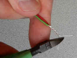
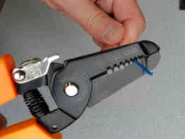
We may remove insulation from the ends of the wire with wire strippers.
Using a knife to strip the insulation is an unacceptable method since the knife will certainly damage a wire.
Professional wire strippers are the best wire stripping tool. It comes with a gauge slot and draws the wire and insulation apart as it cuts.
Now you have a deep groove in the insulation jacket. Keep holding wire strippers a little less tightly and pull with stripper’s jaws towards the end of the wire. That will pull the section of insulation you want to remove away from the wire.
You should have an exposed section of wire ready for soldering.
A wire could be damaged during a wire stripping operation if an incorrect tool or technique is used.
Wire strippers usually come with a gauge index. You should run the wire through the appropriate gauge slot. Grasp the wire with the jaws of the wire strippers at the cutaway point. Clamp the jaws of the wire strippers down.
The wire should be pulled perpendicular to the wire strippers. It may be helpful to use a rotating motion to cut most of the way through the outer insulation.
Insulation from wire-wrap wire can't be removed with wire strippers since this wire is very thin (30 AWG).
A wire-wrap tool should be used to remove insulation from this wire.
Most of the damages to solid wire result in scraping the surface of the wire. During manufacturing in the factory, the surface of copper wire is plated with a thin layer of another metal (usually tin) to protect the copper from oxidation. When this plating is scraped, the copper is exposed to oxidation.
If you cut into the wire you will decrease the electrical and mechanical capabilities of the wire. It will decrease the cross-section of the wire for a current flow and therefore the wire becomes less conductive.
Preparation for Soldering Wires
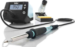
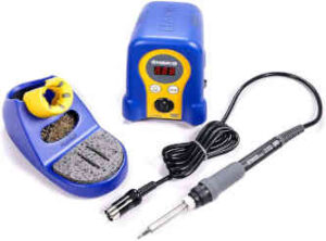
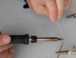
Soldering iron
Soldering iron is the most important piece of tools when soldering wires. Quality soldering can be achieved using good tools.
You don’t need one of the fancy soldering stations for soldering two wires together. However, don’t use the cheapest soldering iron on the market because you may save a few dollars. Too many times I have seen soldering projects ruined by people‘s attempts to use cheap irons.
You can buy a decent temperature-controlled iron for around 50 dollars and use it later for other soldering projects such as soldering wires to circuit boards.
In any case, you will need a soldering iron with interchangeable tips for a variety of wire sizes and heat ranges.
You can use an iron with a small tip for soldering wires with a smaller diameter.
Use a large tip for soldering wires with large diameters since heavy soldering joints need more heat.
Keep iron in the iron stand whenever is not in use.
Solder in a well-ventilated area or use a bench-top fume absorber (also known as smoke extractor}.
Soldering wires don’t require many tools. You will need some specific items such as wire strippers, wire cutters and helping hand tool. These tools are not expensive, it is easy to find them and learn how to use them.
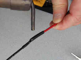
Heat-shrink tubing
Heat-shrink is flexible plastic tubing that comes in various diameters. It will shrink 50% or more when heat is applied to it. Heat-shrink is used to insulate wires.
Cut a piece of heat-shrink tube that is long enough to cover the junction of two wires.
Insert the shrinking tube on the wire before soldering.
Once when two wires are soldered and connected, you will not be able to put a shrinking tube on the wire if the other end of the wire is already connected.
How to tin wire
Tinning the wires is the next step. Any wire that will be connected to another wire or circuit board should be tinned. Tinning should be done before the wire is connected.
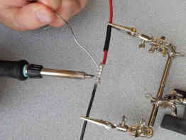
It is recommended to use a soldering helping hand or similar tool which will hold the wires.
It would be a challenge to solder wires together by laying them directly on your workbench. You will burn your workbench and produce bad solder joints.
For wire tinning, choose a chisel tip 3/32” (2.38 mm).
Replace the iron tip before turning on the iron (while the iron is still cool).
Turn on the soldering iron and wait until is fully heated. If using temperature controlled soldering iron, set temperature in the range 660-750 °F (350-400 °C).
Add some water to the sponge in the iron stand to make it moist.
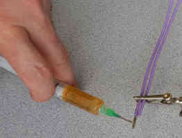
Add a small amount of rosin flux to the end of the wire. Rosin flux (also known as calophonium) is made from pine tree resin.
Touch the iron’s tip to one end of the wire close to insulation, hold for a couple of seconds. The rosin flux will melt and start smoking. That is an indication the flux is activated.
Now you can start adding the solder. The solder should be applied to the wire, not to the iron’s tip.
Slide iron’s tip towards the end of wire i.e. away from insulation. When using this tinning technique, no solder will be pushed up under the insulation. Leave a small gap between the end of the insulation and the beginning of the tinning.
Continue tinning until the wire end is fully coated. The wire should be shiny after tinning.
Repeat this step on the other wire.
How to Solder Wires Together
After tinning both wires, we will connect them and later solder them.
Connecting wires can be divided into two groups: butt splices and tap splices. Butt splices are any connections in which wires are connected end to end while tap splices are those connections in which one wire is inserted into an existing wire run.
How to solder solid wire to solid wire
The simplest way of connecting two solid wires is the pigtail splice. For this connection you should:
Strip equal length of insulation on both wires using wire strippers
Tin both wires
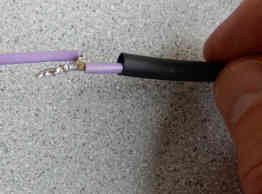
Insert a piece of heat shrink tube on one of the wires
Twist wires four or five times with fingers (for thick wires you may use pliers instead of fingers)
Cut the excess wire
Apply a drop of solder flux on top of the wire connection
Solder wires. Place tip of soldering iron at the middle of the connection to activate the flux. Slide the iron to the end of the connection and then to the other end. Add the proper amount of solder into the connection. Move the iron to the opposite (bottom) side of the connection and repeat the same technique. You should cover all of the wires with solder. When properly soldered, the connection should be smooth and shiny.
Fold over the wire connection
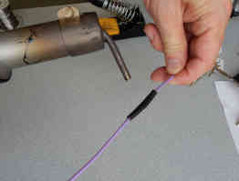
Slide the heat shrink tube over the junction and apply heat with a heat gun. Heat shrink will insulate and protect the wire junction. Move the heat gun along and around the heat-shrink tube, don’t just let it point at one area.
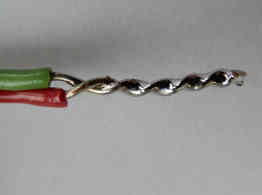
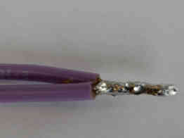
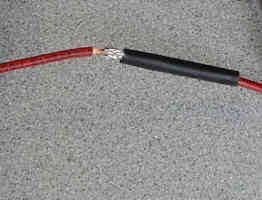
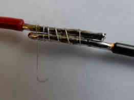
How to solder stranded wire to solid wire
Soldering stranded wire to solid wire is a little bit more difficult than soldering stranded wire to another stranded wire or soldering solid wire to another solid wire.
When soldering a stranded wire to solid wire you should:
Strip about 2” (5 cm) of insulation on both wires
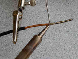
Tin solid wire only. If you tin stranded wire it will change the flexibility - it will become more rigid.
Place the stranded wire over the stranded wire (stranded wire is more flexible than solid wire)
Wrap the stranded wire four or five times around solid wire-strip
Bend the solid wire back
Cut the excess of solid wire at the point where the first stranded twist starts
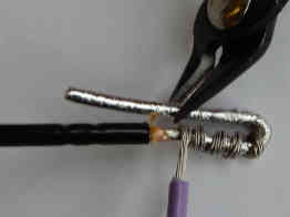
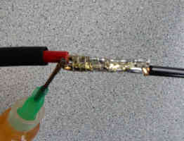
Apply a drop of solder flux on top of the wire connection
Place tip of soldering iron at the top of the connection and solder wires.
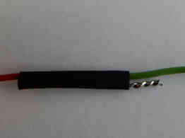
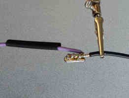
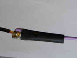
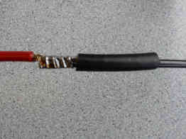
Slide the heat shrink tube over the junction and apply heat with a heat gun.
How to solder stranded wire to stranded wire
Simple technique
Strip about 5/8 of an inch (1.60 cm) of insulation on both wires. The recommended length of a soldered part of the junction is half of an inch. The rest of the striped wire forms a gap between the soldered portion of the connection and insulation.
Don’t cut any stray strand of stranded wire because it will decrease the conductivity of the wire
Twist wires together several times with fingers
Apply a small amount of rosin flux on the upper side of the connection, When heated, the flux will change from solid to liquid state and, caused by gravity, will flow fully over the solder joint. The flux melts at a lower temperature than the solder.
Place soldering iron to the exposed connections
After a couple of seconds apply some solder. The connection of two wires should be covered with solder all around
Remove the soldering iron
Insulate the connection with a heat-shrink tube
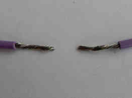
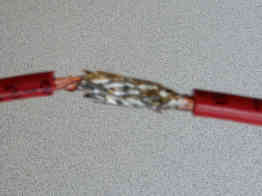
Mesh splice technique
Another way of connecting two stranded wires is the mesh splice technique. For this connection you should:
Strip about 5/8 " (1.60 cm) of insulation on both wires
Insert a piece of heat shrink tube on one of the wire
Connect stranded wires together as shown on the images
Apply a small amount of solder flux. Applying too much flux results in an unwanted process. Liquid solder will go as far as the flux has gone and this leads to unwanted capillary action.
Place soldering iron to the exposed connections and solder wires
Slide the heat shrink tube over the junction and apply heat with a heat gun
How to solder two wires together
Another technique of soldering two wires together is the lap splice. This technique is good for both, stranded wires and solid wires.
When soldering wires with a big diameter, it is not easy to bend or twist them. So the following
technique may be a good technique when soldering ticker wires.
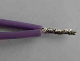
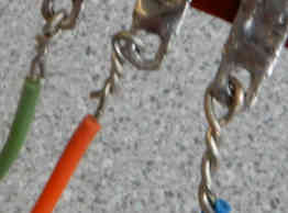
Lap splice technique
Strip about 3/4 “ (1.90 cm) of insulation on both wires
Tin both wires
Insert a piece of heat shrink tube on one of the wire
Connect together stranded wire and solid wire as shown in the third picture
Use a thin solid wire (28 AWG-30 AWG) and wrap it around both wires. Make seven or eight turns and cut the excess of the wire
Apply a small amount of solder flux
Solder the wires. Leave a correctly sized solder gap between insulation and solder joint. You should cover all of the wires with solder, but still, be able to see the strands when finished
Slide the heat shrink tube over the junction and apply heat with a heat gun
Sometimes, it will be required to make several wire connections in the same area.
In this case, the recommendation is to stagger the connections. The junction of wires is thicker than the wire itself. Concentrating all connections in the same point creates a thick bulge and in some cases may lead to a short circuit.
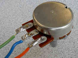
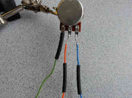
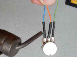
How to solder wires to components
Many electronic components have terminals for connection. They are usually mounted on a front panel or a chassis of an electronic device as external components and should be connected with wires to the rest of the circuit on the PCB (printed circuit board).
These components are switches, potentiometers, audio sockets and other connectors, speakers, buzzers and more.
For this type of connection (wire to terminal) is better to use stranded wire than solid wire since it is more flexible and vibration-resistant. Solid wire can be used as well, but it is easier to work with stranded wire.
For successful soldering, both surfaces should be clean: the terminal and the wire. Inspect terminals of the component and ensure that they are clean. If not, use isopropyl alcohol or other approved cleaner to remove all contamination.
If an electronic component has been in storage for a long time, it may have more contamination and oxidation caused by environmental factors.
Use a glass-fibre brush, paintbrush or other plastic brush to remove stubborn contamination. (don’t use sandpaper or steel brush).
Place component to be soldered in the helping hand tool or another holder to keep the component in place while soldering.
The same techniques of soldering apply to most of the external electronic components that come with terminals. The two most popular techniques of soldering wires to terminals are explained below.
Simple technique
This technique is a quick and easy way of soldering wire to the terminal.
It is also easier to de-solder the connection if needed when replacing the component or repairing the device.
It provides a good and reliable connection in most of the applications in the electronics industry. Those are the reasons why this technique is used in the majority of wire-to-terminal joints in commercial electronic devices.
Strip about 1/4” (6 mm) of insulation from the connecting wire
Tin the stripped end of the wire. If using a stranded wire, tinning will change the flexibility of stripped end of the wire- it will become more rigid
Apply a small amount of rosin flux to terminal
Tin the terminal with a thin layer of solder. If the terminal has a hole in it, keep the hole open (don’t fill it with solder)
Run the wire end through the hole in the terminal. Cut the excess wire if needed.
Take a soldering iron and place the iron tip to the junction. Ensure the iron tip touches both surfaces (the terminal and the wire end) simultaneously
After a couple of seconds, apply just a small amount of the solder to the junction. A small amount of solder is good enough since both surfaces are already tinned
Protect solder joint with heat-shrink tube. A heat-shrink tube will protect the solder joint from shorts and oxidation. The heat-shrink tube should be a little bit longer than the exposed wire. Trim any spikes or sharp strands of wire before you cover the junction with heat-shrink since they can poke through the heat-shrink tube and cause shorts. Apply heat to the heat-shrink tube with a heat gun. (If the other end of the wire is already attached to the circuit, you should slide heat-shrink tube on wire prior to soldering)
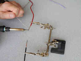
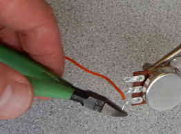
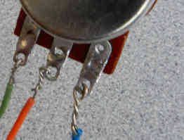
Technique for a stronger connection
Strip about 3/4 “ (1.90 cm) of insulation on the wire
Tin the terminal with a thin layer of solder. If the terminal has a hole in it, keep the hole open (don’t fill it with solder)
Run the wire through the hole in the terminal. If there is no hole for the wire to go through, then you should wrap the wire around the terminal
Twist the wire 5 times
Cut the excess wire
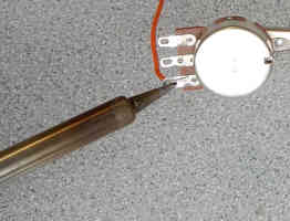
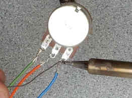
Apply a small amount of solder flux to the connection
Place the tip of the soldering iron to the connection. Heat both, the wire and the terminal, simultaneously
Add solder to the connection. Solder will start melting and flowing to the wire and terminal
Protect solder joint with heat-shrink tube (as explained earlier in this guide)
How to solder wire to board
Wires could be connected directly to the metalized holes on the circuit board.
In the first step, you should tin the end of the wire. The metalized holes have already been pre-tinned with a thin layer of solder in the factory during manufacturing.
Tinning is the action of melting a bit of solder onto the wire end first before soldering it to the circuit board.
Tinning ensures that the end of the wire is without oxidation and it allows the solder to attach faster to finish with a far better result.
Stranded wires should be twisted with fingers prior to tinning.
After tinning the wire, insert the wire into the metalized hole on the circuit board.
Place tip of soldering iron to the solder joint.
After a couple of seconds apply a very small amount of solder to the solder joint.
Use a solder wire which contains rosin flux in its core to minimize oxidation during soldering.
The wire’s insulation may shrink back a little bit caused by the heat of soldering iron, so do not overheat the soldering joint by keeping solder iron for a longer time than is required.
Remove soldering iron and wait a few more seconds for solder to solidify.
Clean solder joint from flux residues using alcohol or flux remover pen.
Stranded vs solid wire
A wire is the most commonly used conductor type in electronics.
Wires are made of metal. Each type of metal has certain benefits and shortcomings.
The majority of wires are made of copper. Copper has very low resistance to current flow and relatively low costs.
Aluminum is also a good conductor so some wires are made of aluminum. Since aluminum has lower conductivity than copper, the aluminum wire needs a larger cross-section to compensate. The majority of aluminum wires are used in residential electrical systems.
Silver is the perfect conductor. It is a much better conductor than copper. However, silver is too expensive for wire production.
Some electronic components have their pins plated with a very thin layer of gold, however, no wires have been made of gold.
All wires are divided into solid wires and stranded wires. Each wire has advantages and deficiencies.
Which wire is better to use: stranded vs solid wire.
Solid wire is easier to manufacture than stranded wire, so it is cheaper. The disadvantage of solid wire is that it may be bent only a few times without damage.
The stranded wire is more flexible than solid wire and it could be bent several times without damage. It is a better conductor at higher frequencies than solid wire because it has many strands. As the frequency increases, the current is forced to flow on the surface of the wire. More strands in stranded wire mean more surface area for current to flow at high frequencies.
In addition, wires can be divided:
insulated wires
magnet wire
The magnet wire has a very thin layer of varnish or enamel as insulation. It is often called “bare wire” since it comes without any plastic or rubber insulation and looks like bare wire.
If we use a bare wire for coils in transformers and inductors, we would not be able to make the turns of the wire without touching each other.
The adjacent turns of wire will touch each other and as result, they will make a short circuit. If we use insulated wire instead of bare wire, we can wound many turns of wire and don’t care if they touch each other.
For a wire that will have several turns, insulation is absolutely necessary.
Wire gauge
Wires come in a variety of types and sizes. Some electrical circuits conduct higher electrical current so they need a ticker wire. The diameter of the wire determines the size of the wire.
American Wire Gauge (AWG) is a standard used in the United States and Canada as a measure of the wire size. Solid and stranded wires both use the same AWG standard.
A bigger AWG number means a smaller diameter of the wire. The most common gauge of wire used in electronics is AWG 22.
Selecting a wire with a proper AWG size is important in all circuit designs.
The selection of a proper gauge is based on the maximum current ratings for the circuit.
If the designer selects a too small diameter of wire it may lead to circuit failure.
Wire insulation
Most of the wires come as insulated wires. The function of insulation is:.
to prevent short circuits
to prevent exposure of people to dangerous high voltages and electrical currents
to protect the wire from the atmospheric and other environmental factors
High voltage can break insulation and make a short circuit. That is a reason why each wire must have specified a maximum operating voltage.
PVC (polyvinyl chloride), rubber and teflon are the most common insulation used on wires in electronics.
SINI SAJA Sini is a passionate Electrical Engineer with over 40 years of experience in the electronics industry and in 3 countries. He holds B. Sc. in Engineering and is a member (P. Eng) of the Association of Professional Engineers of Canada.
Sini Saja wrote several articles on Instructables.com and EzineArticles.com. He earned a silver medal for over 1 million views on Instructables. See profile here.